What is a Motor?
A motor converts electrical energy into mechanical motion. Motors are essential in robotics for movement and control.
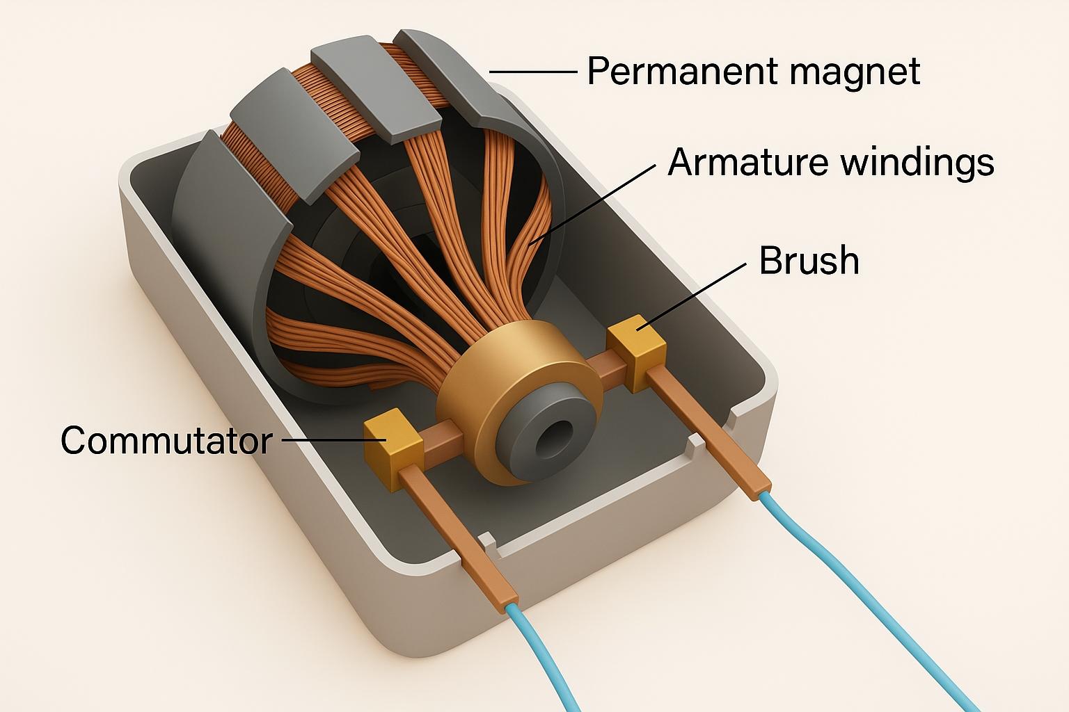
The Physics: How Motors Work
When electric current flows through a wire in a magnetic field, the wire experiences a force that pushes it. This force creates rotation in motors.
The Formula: F = I × L × B
• F = Force (how hard it pushes)
• I = Current (electricity flowing)
• L = Wire length in magnetic field
• B = Magnetic field strength
Fleming's Left-Hand Rule (Direction Finder)
Thumb = Force/Motion direction
First finger = Magnetic field (North to South)
Middle finger = Current direction (+ to −)
Hold these three fingers perpendicular to find the force direction!
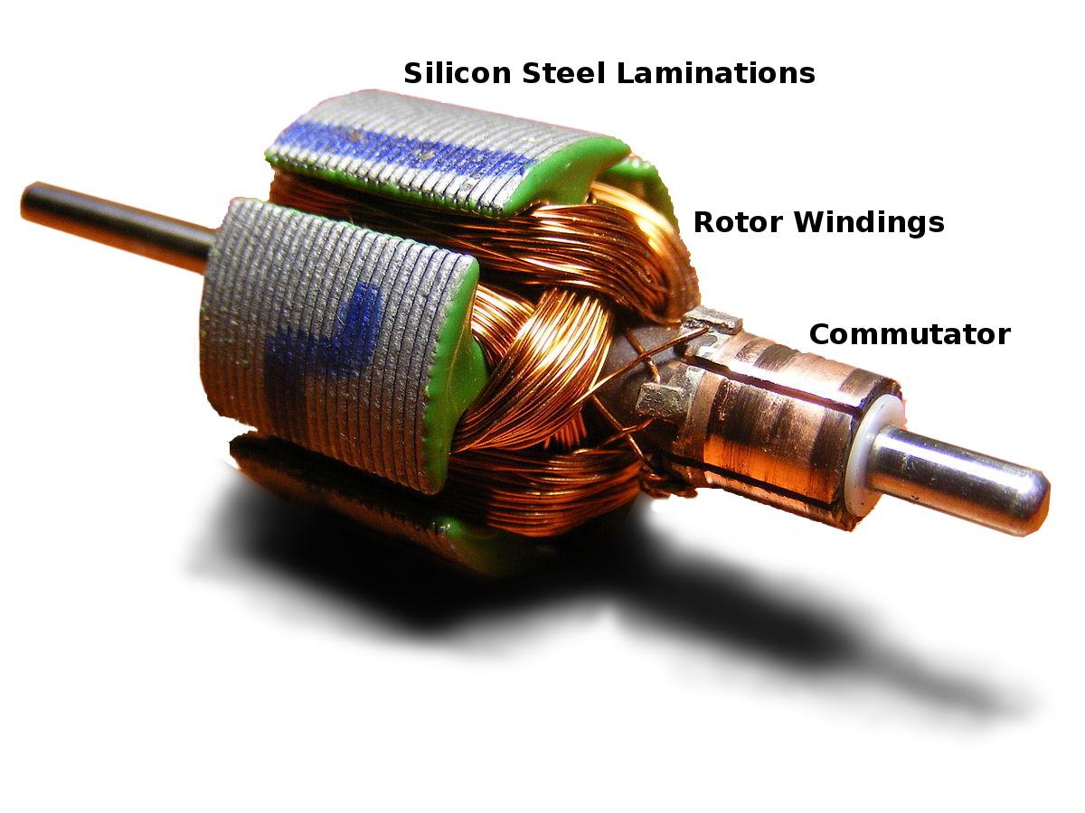
Internal Components
Stator coils, rotor windings, commutator, and brushes work together using electromagnetic principles
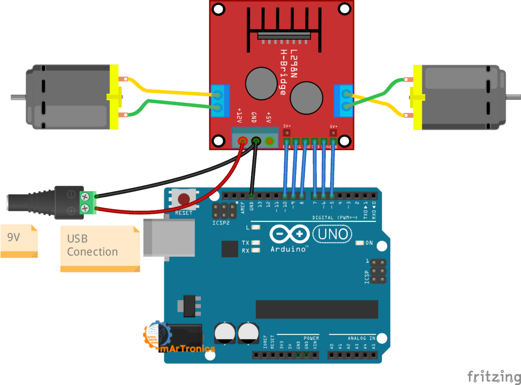
Control Circuit
Electronic circuits regulate speed, direction, and torque using PWM and H-bridge configurations
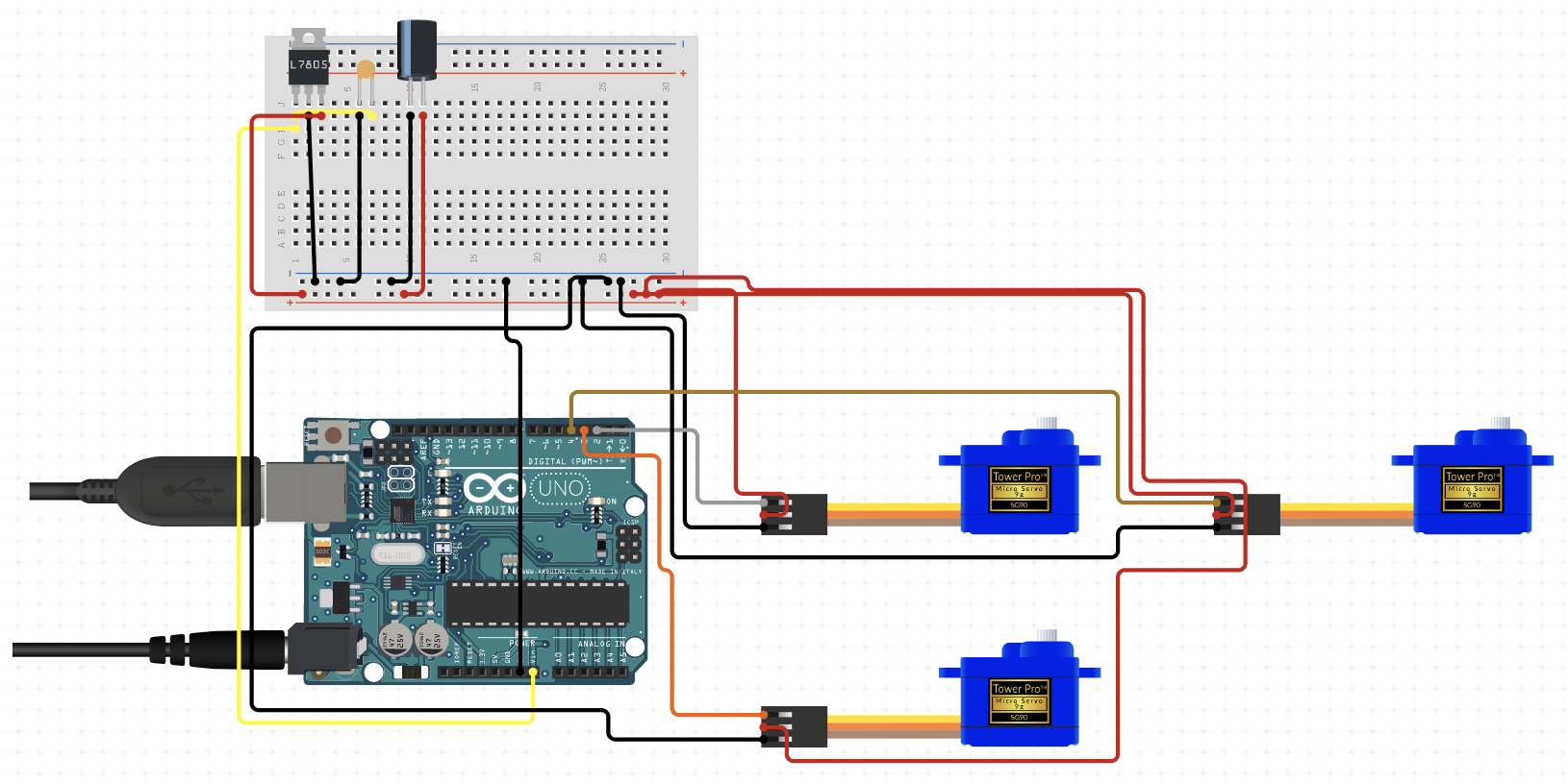
Robotic Arm Circuit
Multiple motors coordinated for complex movements in multi-axis systems
How Motors Create Rotation
-
1
A coil of wire (armature) sits between magnetic north and south poles
-
2
Electric current flows through the coil
-
3
Lorentz force pushes opposite sides of the coil in opposite directions
-
4
This creates torque (twisting force) that makes the coil spin
-
5
The commutator switches current direction every half turn to keep spinning
Types of Motors in Robotics
Choose your motor based on what you need: speed control, precise positioning, or high torque.
PWM Control
Learn how Pulse Width Modulation controls motor speed by varying the duty cycle. Essential for understanding speed control in DC motors.
View CardMotor Selection
Quick reference for choosing the right motor type based on your project requirements: DC, servo, stepper, or brushless.
View CardMotor Drivers
Understand why motor drivers are necessary and how to select the right driver (L298N, A4988, TB6612) for your motors.
View Card💡 Tip: Open each card in a new tab, then right-click and select "Save as..." or take a screenshot to save as an image for offline reference.
DC Motors
DC (Direct Current) motors are the most common type used in robotics. They convert direct current electrical energy into mechanical rotation through electromagnetic induction and the Lorentz force acting on current-carrying conductors in a magnetic field.
How DC Motors Work (Physics Explanation)
1. Magnetic Field: Permanent magnets or field coils create a stationary magnetic
field with north and south poles.
2. Current Flow: When DC voltage is applied, current flows through the armature
windings (coils wound around an iron core).
3. Lorentz Force: The interaction between the magnetic field and the current-carrying
armature generates a force on each conductor. Using Fleming's Left-Hand Rule, forces on opposite sides
of the armature act in opposite directions.
4. Torque Creation: These opposing forces create a torque around the motor shaft axis,
causing rotation. Torque is maximized when the coil plane is perpendicular to the magnetic field.
5. Commutation: The commutator (split ring) reverses current direction in the armature
every 180° of rotation. This ensures the torque always acts in the same rotational direction.
6. Continuous Rotation: The commutator switching keeps the electromagnetic force aligned
to maintain continuous rotation rather than oscillation.
Back EMF: As the motor rotates, the armature conductors cut through the magnetic field lines, inducing a voltage (electromotive force) that opposes the applied voltage. This is called back EMF or counter-EMF, and it limits the motor's maximum speed and current draw.
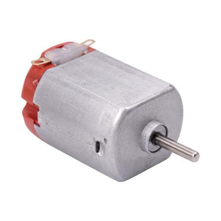
Brushed DC Motor
Simple, cost-effective design with physical carbon brushes that make contact with the commutator
Geared DC Motor
Gear reduction increases torque and reduces speed, ideal for high-load applications
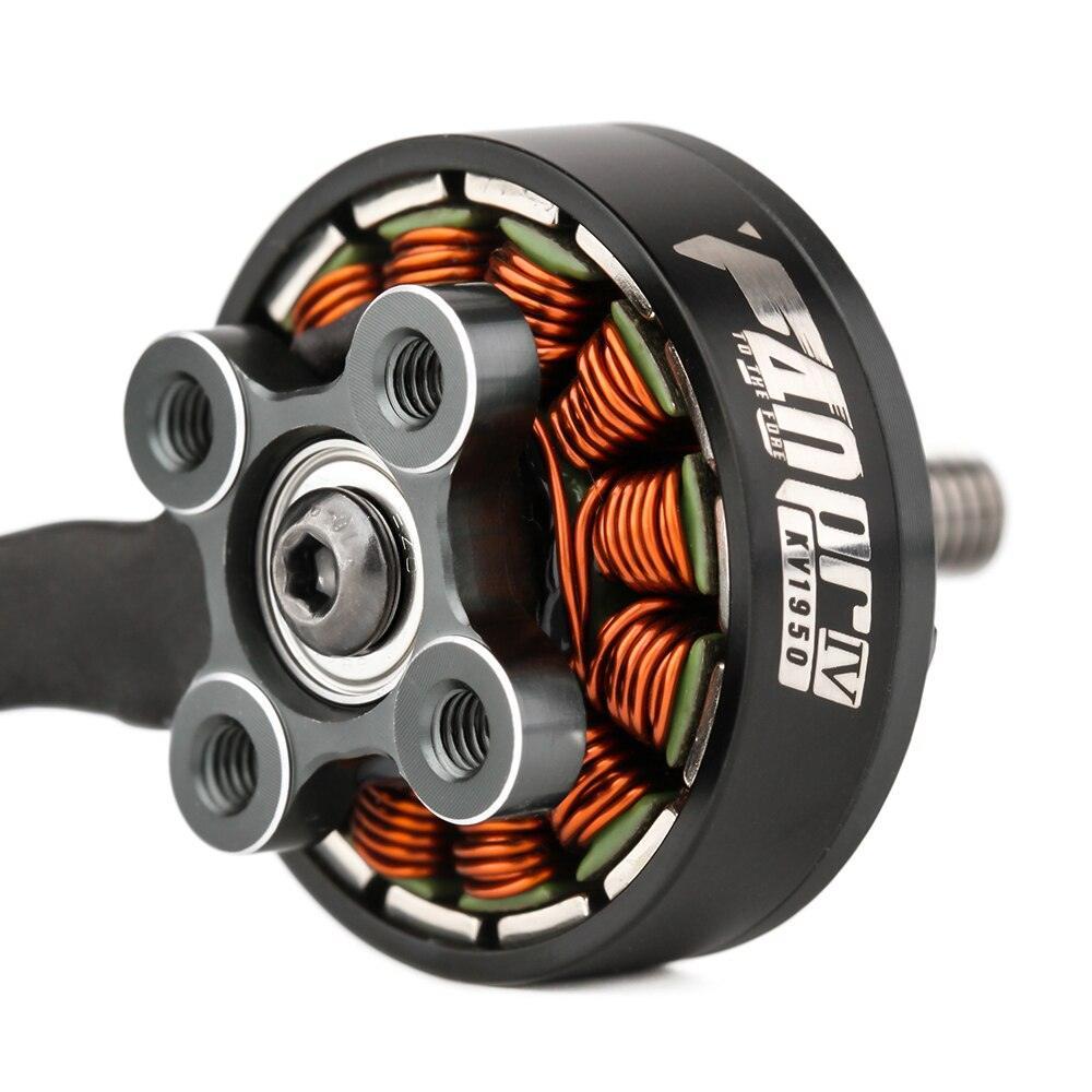
Brushless DC Motor (BLDC)
Electronic commutation replaces brushes, providing higher efficiency and longer lifespan
DC Motor Variants
BLDC Internal Structure
Stator coils surround a permanent magnet rotor; electronic controller switches coil energization
Geared Motor Assembly
Planetary or spur gears multiply torque through mechanical advantage
DC Motor Circuit Diagram
Electrical schematic showing field windings, armature, and control connections
Applications in Robotics
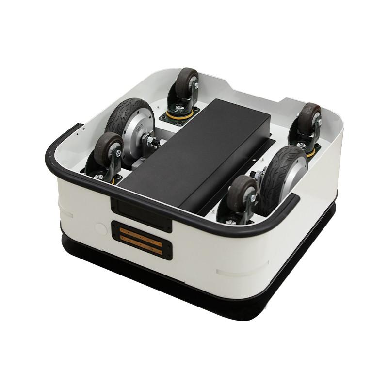
Mobile Robots
Geared DC motors drive wheels in autonomous delivery robots and AGVs (Automated Guided Vehicles)
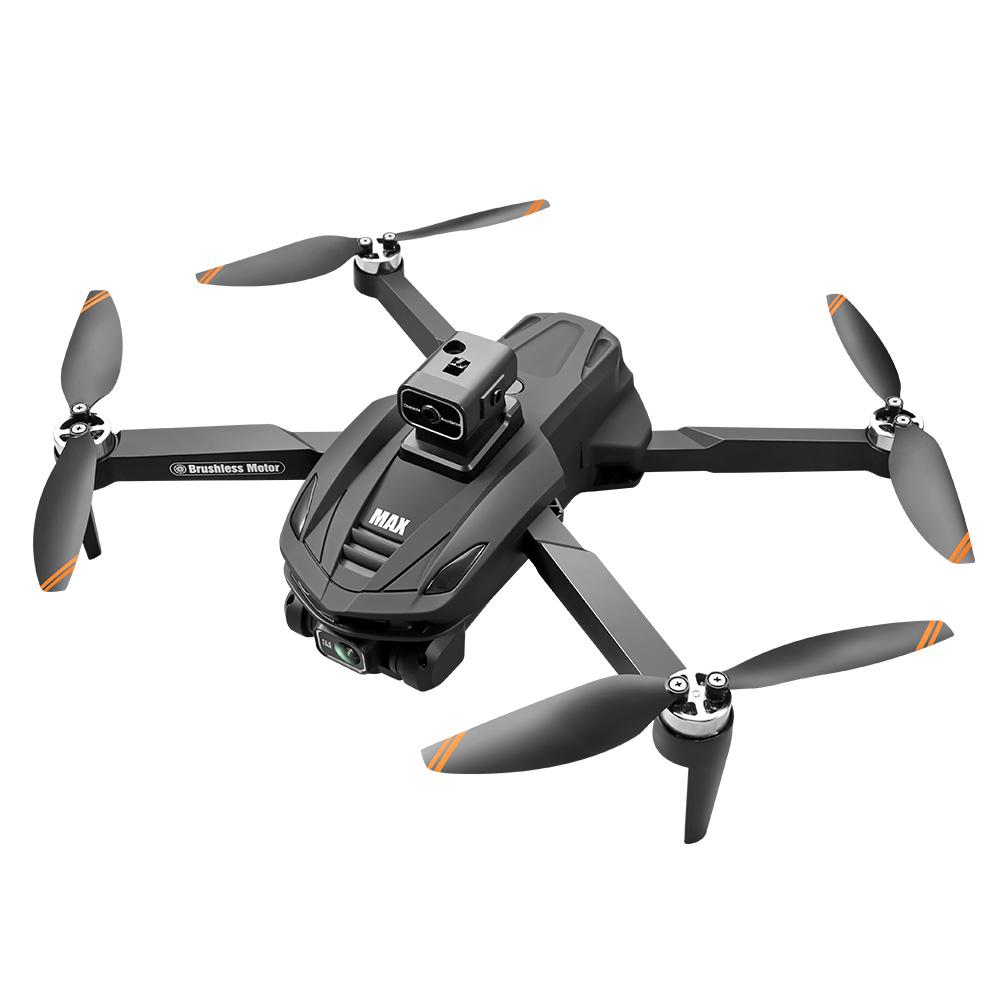
Drones & UAVs
High-speed brushless DC motors provide thrust for quadcopters with excellent power-to-weight ratio
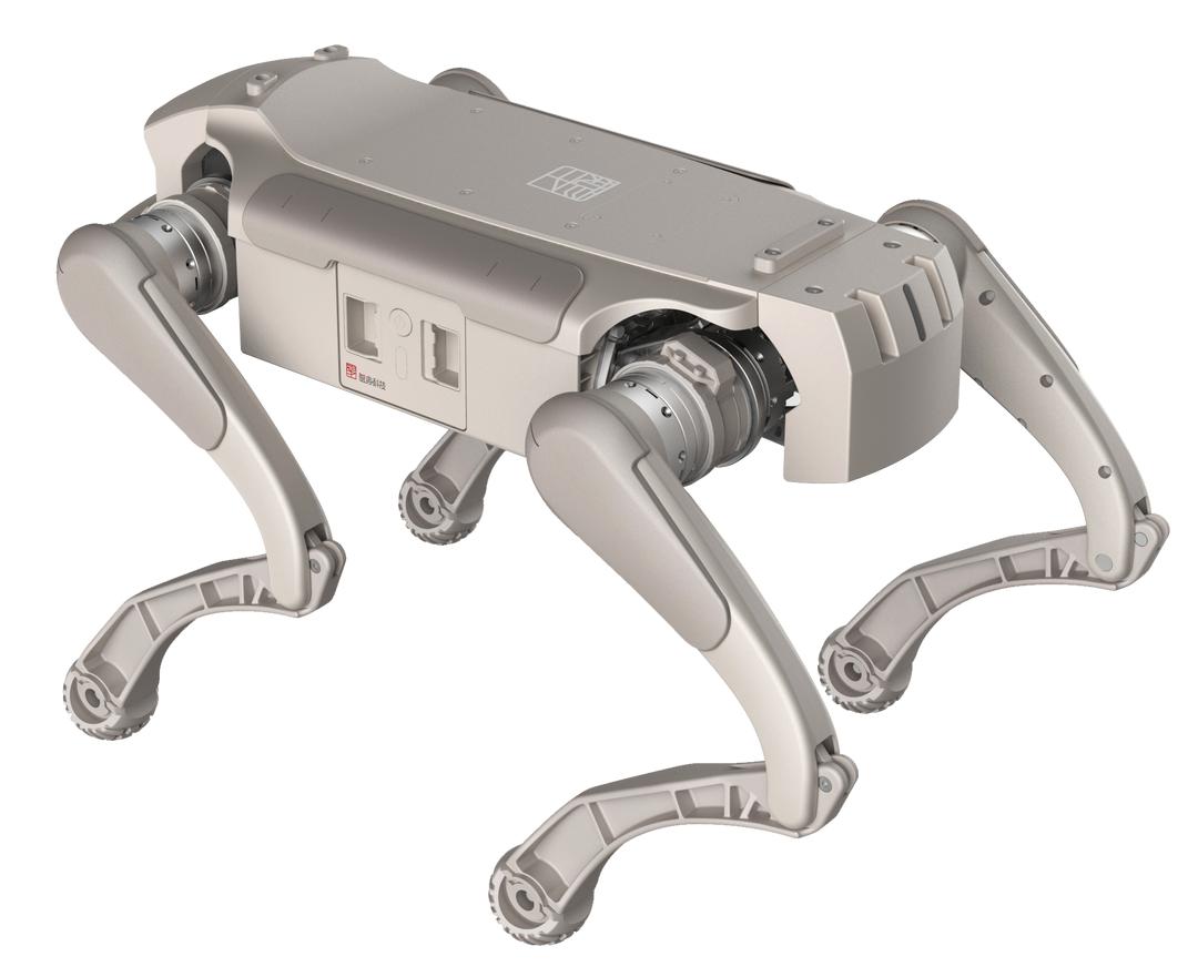
Robotic Manipulators
Geared motors provide high torque for joint actuation in robotic arms and grippers
Hands-On Project: 4-Wheel Robot Car
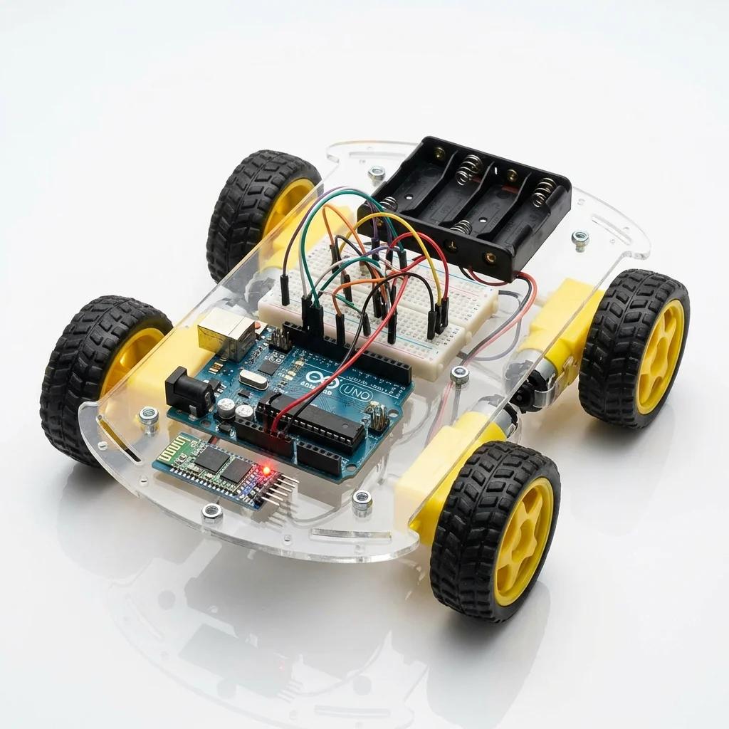
Build a mobile robot platform using four DC motors controlled by dual L298N motor drivers. This project demonstrates differential drive control, allowing forward, backward, left turn, and right turn movements through independent control of left and right motor pairs.
Components Required
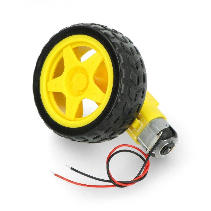
• Microcontroller: Arduino Mega 2560 (or Uno with pin adjustments)
• Motors: 4× DC gear motors (typically 6V, 200 RPM)
• Motor Driver: 2× L298N dual H-bridge modules (one per motor pair)
• Power Supply: 7.4V LiPo battery or 6× AA batteries (6-9V)
• Chassis: 4WD robot car chassis kit with wheels
• Wiring: Jumper wires, battery connector
• Optional: Bluetooth module (HC-05), ultrasonic sensor for obstacle avoidance
Wiring Connections
Left Side Motors (Front Left + Rear Left):
• L298N Module 1 ENA → Arduino Pin 5 (PWM for speed control)
• L298N Module 1 IN1 → Arduino Pin 10
• L298N Module 1 IN2 → Arduino Pin 11
• Motors connected to OUT1 and OUT2
Right Side Motors (Front Right + Rear Right):
• L298N Module 1 ENB → Arduino Pin 6 (PWM for speed control)
• L298N Module 1 IN3 → Arduino Pin 12
• L298N Module 1 IN4 → Arduino Pin 13
• Motors connected to OUT3 and OUT4
Power:
• Battery (+) → L298N +12V input
• Battery (−) → L298N GND AND Arduino GND (common ground essential)
• Arduino powered separately via USB or barrel jack during programming
• Remove L298N 5V jumper if using external Arduino power
Complete Arduino Code
// 4-Wheel Robot Car with Differential Drive Control
// Uses L298N dual H-bridge motor driver for independent left/right control

// Left motors (Motor A on L298N)
const int ENA = 5;   // PWM pin for left motors speed
const int IN1 = 10;  // Left motors direction pin 1
const int IN2 = 11;  // Left motors direction pin 2

// Right motors (Motor B on L298N)
const int ENB = 6;   // PWM pin for right motors speed
const int IN3 = 12;  // Right motors direction pin 1
const int IN4 = 13;  // Right motors direction pin 2

// Speed setting (0-255)
// Adjust this value based on your motors and surface
int speed = 170;  // ~67% power, good balance of speed and control

void setup() {
  // Configure all motor control pins as outputs
  pinMode(ENA, OUTPUT);
  pinMode(IN1, OUTPUT);
  pinMode(IN2, OUTPUT);
  pinMode(ENB, OUTPUT);
  pinMode(IN3, OUTPUT);
  pinMode(IN4, OUTPUT);

  // Start with motors stopped
  stop();

  Serial.begin(9600);
  Serial.println("4-Wheel Robot Car Initialized");
}

/**
 * Move forward - both motor pairs rotate forward
 * Differential drive: Left motors CW, Right motors CW
 */
void start() {
  Serial.println("Moving Forward");
  // Left motors forward
  digitalWrite(IN1, HIGH);
  digitalWrite(IN2, LOW);
  // Right motors forward
  digitalWrite(IN3, HIGH);
  digitalWrite(IN4, LOW);
  // Apply speed to both sides
  analogWrite(ENA, speed);
  analogWrite(ENB, speed);
}

/**
 * Stop all motors
 * Sets all control pins LOW and PWM to 0
 */
void stop() {
  Serial.println("Stopped");
  analogWrite(ENA, 0);
  analogWrite(ENB, 0);
  digitalWrite(IN1, LOW);
  digitalWrite(IN2, LOW);
  digitalWrite(IN3, LOW);
  digitalWrite(IN4, LOW);
}

/**
 * Turn right - differential drive
 * Left motors forward, Right motors backward
 * Creates rotation around center axis
 */
void moveright() {
  Serial.println("Turning Right");
  // Left motors forward
  digitalWrite(IN1, HIGH);
  digitalWrite(IN2, LOW);
  // Right motors backward (reverse)
  digitalWrite(IN3, LOW);
  digitalWrite(IN4, HIGH);
  // Full speed for sharp turn
  analogWrite(ENA, speed);
  analogWrite(ENB, speed);
}

/**
 * Turn left - differential drive
 * Left motors backward, Right motors forward
 * Creates rotation around center axis
 */
void moveleft() {
  Serial.println("Turning Left");
  // Left motors backward (reverse)
  digitalWrite(IN1, LOW);
  digitalWrite(IN2, HIGH);
  // Right motors forward
  digitalWrite(IN3, HIGH);
  digitalWrite(IN4, LOW);
  // Full speed for sharp turn
  analogWrite(ENA, speed);
  analogWrite(ENB, speed);
}

/**
 * Move backward - both motor pairs reverse
 */
void reverse() {
  Serial.println("Moving Backward");
  // Left motors backward
  digitalWrite(IN1, LOW);
  digitalWrite(IN2, HIGH);
  // Right motors backward
  digitalWrite(IN3, LOW);
  digitalWrite(IN4, HIGH);
  // Apply speed
  analogWrite(ENA, speed);
  analogWrite(ENB, speed);
}

void loop() {
  // Demonstration sequence

  // Move forward for 2 seconds
  start();
  delay(2000);

  // Quick right turn
  moveright();
  delay(500);

  // Quick left turn
  moveleft();
  delay(500);

  // Stop for 2 seconds
  stop();
  delay(2000);

  // Add your own patterns:
  // - Square pattern navigation
  // - Figure-8 pattern
  // - Obstacle avoidance with sensors
}
How Differential Drive Works
Differential drive uses independent control of left and right wheel pairs to achieve
steering without a separate steering mechanism:
• Forward: Both sides rotate forward at same speed → straight line
• Backward: Both sides rotate backward at same speed → straight reverse
• Pivot Turn Right: Left forward + Right backward → rotates clockwise in place
• Pivot Turn Left: Left backward + Right forward → rotates counter-clockwise in place
• Gradual Turn: One side faster than other → curved path (not implemented here)
Advantages: Simple mechanical design, no steering servo needed, can rotate in place (zero turning radius).
Disadvantages: Cannot move sideways, skidding on rough terrain, wheel slippage during turns.
Enhancements & Challenges
Speed Calibration: Motors rarely have identical speeds. Measure actual wheel RPM and
adjust ENA/ENB values independently to ensure straight-line movement.
Add Remote Control: Integrate HC-05 Bluetooth module:
• Receive commands via Serial.read()
• Commands: 'F'=forward, 'B'=backward, 'L'=left, 'R'=right, 'S'=stop
Obstacle Avoidance: Add HC-SR04 ultrasonic sensor:
• Continuously measure distance ahead
• If distance < 20cm: stop(), delay(), moveright(), delay(), resume
Line Following: Add IR line sensors:
• Read left and right sensors
• Adjust motor speeds to keep robot centered on line
Smooth Acceleration: Gradually increase speed from 0 to target using a for-loop to
prevent wheel slippage and reduce mechanical stress.
Basic DC Motor Control Example
For learning purposes, here's a simpler single motor control example that demonstrates the fundamental concepts before building the full robot car.
// DC Motor Control with L298N Motor Driver
// Demonstrates speed control (PWM) and direction control (H-bridge)

// Motor A connections
const int enA = 9;   // PWM pin for speed control (0-255)
const int in1 = 8;   // Direction control pin 1
const int in2 = 7;   // Direction control pin 2

void setup() {
  // Set motor control pins as outputs
  pinMode(enA, OUTPUT);
  pinMode(in1, OUTPUT);
  pinMode(in2, OUTPUT);

  // Initialize motor in stopped state
  digitalWrite(in1, LOW);
  digitalWrite(in2, LOW);

  Serial.begin(9600);
  Serial.println("DC Motor Control Ready");
  Serial.println("Demonstrating PWM speed control");
}

void loop() {
  // Gradually accelerate forward
  Serial.println("Accelerating Forward");
  for (int speed = 0; speed <= 255; speed += 5) {
    motorForward(speed);
    delay(50);
  }
  delay(1000);

  // Gradually decelerate
  Serial.println("Decelerating");
  for (int speed = 255; speed >= 0; speed -= 5) {
    motorForward(speed);
    delay(50);
  }

  motorStop();
  delay(1000);

  // Gradually accelerate backward
  Serial.println("Accelerating Backward");
  for (int speed = 0; speed <= 255; speed += 5) {
    motorBackward(speed);
    delay(50);
  }
  delay(1000);

  // Gradually decelerate
  Serial.println("Decelerating");
  for (int speed = 255; speed >= 0; speed -= 5) {
    motorBackward(speed);
    delay(50);
  }

  motorStop();
  delay(2000);
}

// Function to move motor forward
// H-bridge: IN1=HIGH, IN2=LOW allows current flow in forward direction
void motorForward(int speed) {
  digitalWrite(in1, HIGH);
  digitalWrite(in2, LOW);
  analogWrite(enA, speed);  // PWM controls average voltage (speed)
}

// Function to move motor backward
// H-bridge: IN1=LOW, IN2=HIGH reverses current flow
void motorBackward(int speed) {
  digitalWrite(in1, LOW);
  digitalWrite(in2, HIGH);
  analogWrite(enA, speed);
}

// Function to stop motor
// Both LOW = brake, motor coasts to stop
void motorStop() {
  digitalWrite(in1, LOW);
  digitalWrite(in2, LOW);
  analogWrite(enA, 0);
}

// Alternative brake function
// Both HIGH = active brake, stops motor faster
void motorBrake() {
  digitalWrite(in1, HIGH);
  digitalWrite(in2, HIGH);
  analogWrite(enA, 255);
}
Servo Motors
Servo motors are specialized motors designed for precise angular position control using a closed-loop feedback system. Unlike regular DC motors that rotate continuously, servos move to and hold a specific angle based on a control signal.
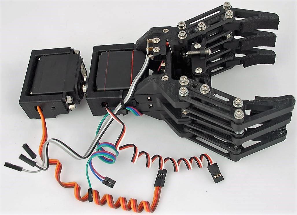
How Servo Motors Work (Closed-Loop Control)
A servo motor is actually a feedback control system consisting of:
1. DC Motor: Provides the rotational force (typically a small brushed DC motor)
2. Gear Reduction System: Increases torque and reduces speed through gear ratios
(typically 100:1 to 300:1). Higher gear ratio = more torque but slower response.
3. Position Sensor: Usually a potentiometer mechanically coupled to the output shaft.
As the shaft rotates, the potentiometer resistance changes, producing a voltage proportional to position.
4. Control Circuit: Compares the target position (from PWM input signal) with actual
position (from potentiometer) and adjusts motor power to minimize error.
PID Control: The servo's internal circuit uses a form of PID (Proportional-Integral-Derivative)
control:
• Error = Target Position - Actual Position
• If error > 0: motor rotates clockwise
• If error < 0: motor rotates counter-clockwise
• As error approaches 0: motor slows down
• When error = 0: motor stops (position reached)
PWM Control Signal
Servos use PWM (Pulse Width Modulation) for position control, but differently than DC motors:
• Frequency: 50 Hz (20ms period)
• Pulse Width: 1000µs to 2000µs (1-2ms)
• 1000µs (1ms): 0° position
• 1500µs (1.5ms): 90° position (center)
• 2000µs (2ms): 180° position
The servo measures the pulse width and moves to the corresponding angle. It continuously reads the signal
and maintains position even under external forces (holding torque).
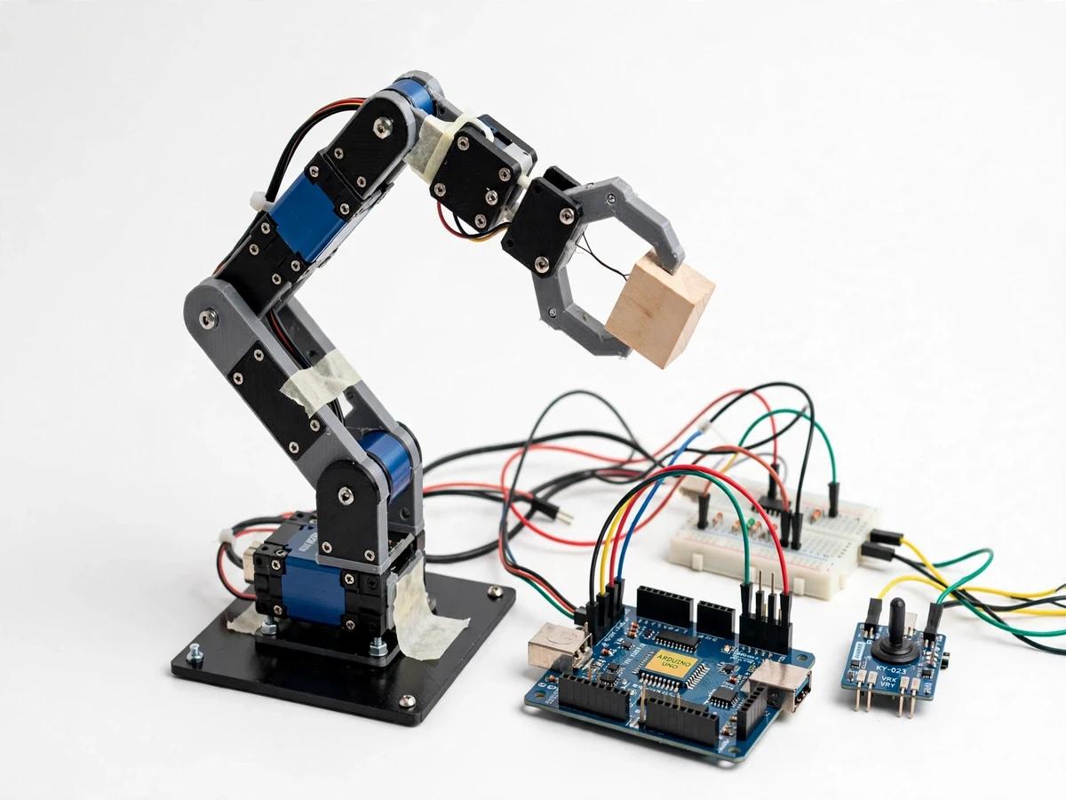
Feedback Control System
Potentiometer provides position feedback; error signal drives motor until target position is reached
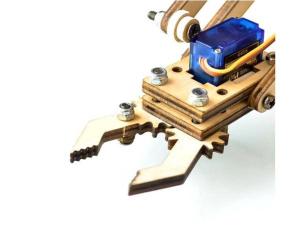
Standard Servo (180°)
Most common type with 180° rotation range, used in RC vehicles and robot joints
Continuous Rotation Servo
Modified servo with potentiometer removed; pulse width controls rotation speed instead of position
Applications in Robotics
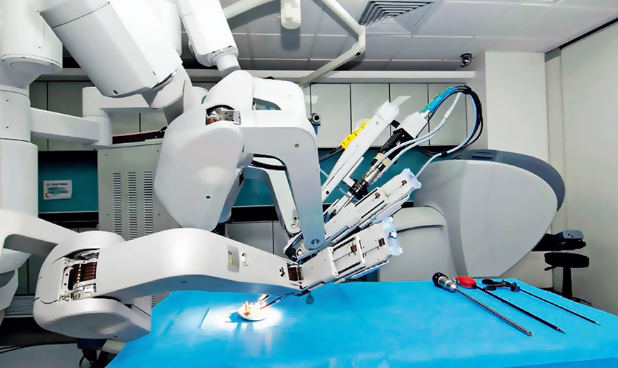
Medical Robotics
High-precision servos enable minimally invasive surgery with sub-millimeter accuracy

Industrial Automation
6-axis industrial robots use AC servo motors for precise pick-and-place operations
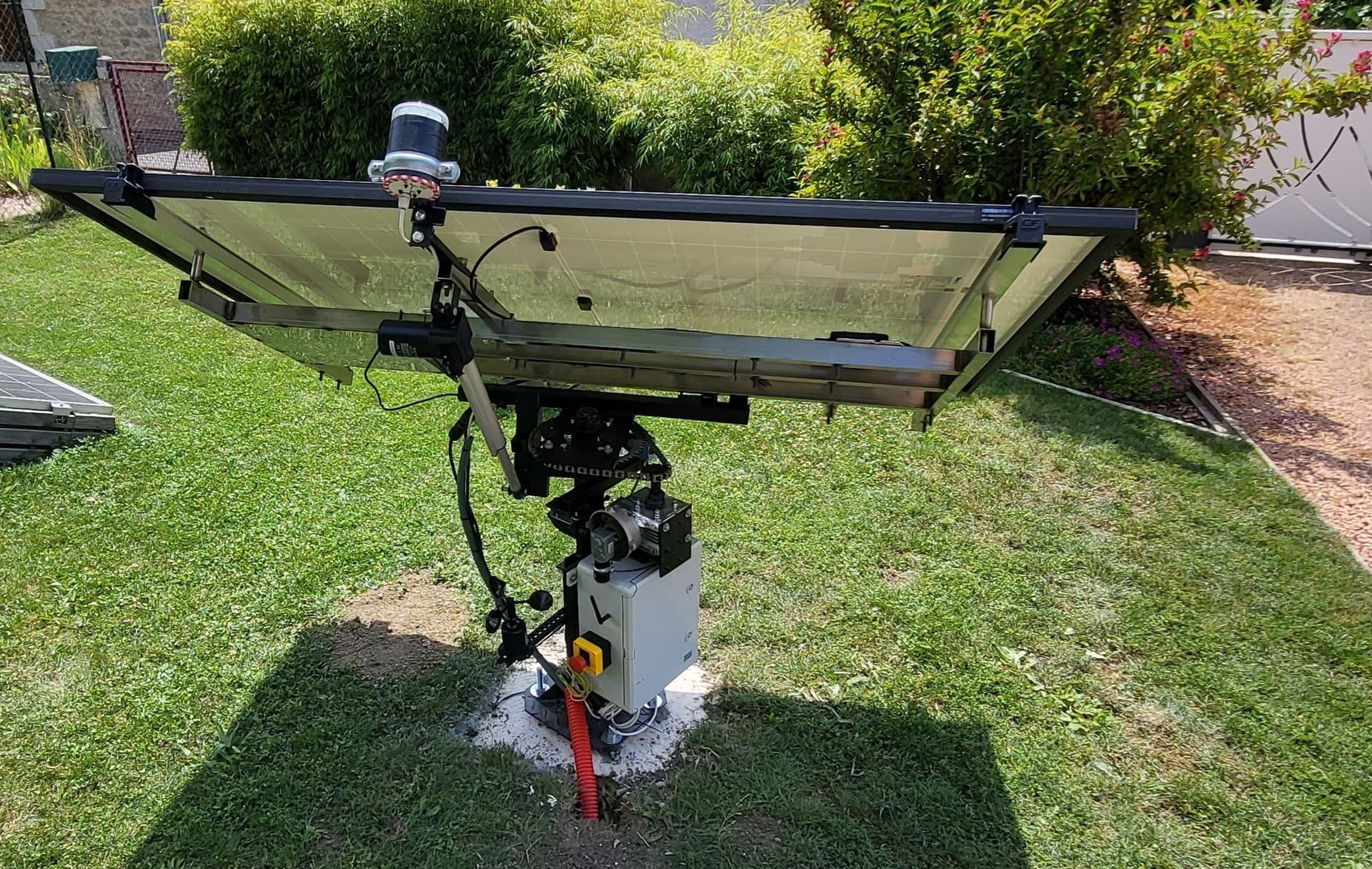
Solar Tracking Systems
Servos adjust panel angles throughout the day to maximize sunlight exposure
Hands-On Project: Servo Motor Sweep
Create a basic servo control project to understand position control and PWM timing. This simple but educational project demonstrates how servos respond to angle commands and hold positions under load.
Components Required
• Microcontroller: Arduino Uno, Nano, or Mega
• Servo Motor: Standard servo motor (SG90 or similar 180° servo)
• Power Supply: External 5V power supply (1A minimum) or Arduino 5V pin for testing
• Wiring: 3 jumper wires (signal, power, ground)
• Optional: Potentiometer for manual angle control, LED indicator for visual feedback
Wiring Connections
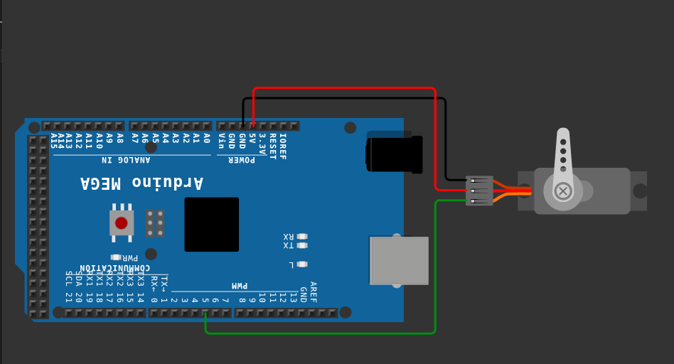
Servo Wire Colors (Standard):
• Orange/Yellow (Signal) → Arduino Pin 9 (any PWM pin works)
• Red (Power/VCC) → External 5V+ OR Arduino 5V pin (for single servo only)
• Brown/Black (Ground) → Arduino GND
Important Power Notes:
• Single SG90 servo draws ~100mA idle, up to 500mA+ under load
• Arduino 5V pin provides max 500mA total (shared with other components)
• For one servo in testing: Arduino 5V is acceptable
• For multiple servos or heavy loads: MUST use external 5V power supply
• Always connect power supply GND to Arduino GND (common ground)
Complete Arduino Code
// Basic Servo Motor Control and Sweep
// Demonstrates servo positioning and PWM control principles

#include <Servo.h>

Servo servomotor;  // Create servo object

const int servoPin = 9;  // Signal pin (must be digital pin)

void setup() {
  // Attach servo to pin 9
  // This configures pin 9 to output 50Hz PWM signal
  servomotor.attach(servoPin);

  Serial.begin(9600);
  Serial.println("Servo Control Ready");
  Serial.println("Servo will move to 0°, 90°, and 180°");

  // Move to center position on startup
  servomotor.write(90);
  delay(1000);
}

void loop() {
  // Move to 0° (full left/minimum position)
  Serial.println("Position: 0 degrees (1000µs pulse)");
  servomotor.write(0);
  delay(1000);  // Wait 1 second at this position

  // Move to 90° (center position)
  Serial.println("Position: 90 degrees (1500µs pulse)");
  servomotor.write(90);
  delay(1000);

  // Move to 180° (full right/maximum position)
  Serial.println("Position: 180 degrees (2000µs pulse)");
  servomotor.write(180);
  delay(1000);

  // Pause before repeating
  delay(500);
}

/**
 * Additional Examples Below
 */

// Smooth continuous sweep
void smoothSweep() {
  // Sweep from 0 to 180 degrees
  for (int angle = 0; angle <= 180; angle++) {
    servomotor.write(angle);
    delay(15);  // 15ms per degree = ~2.7 seconds per sweep
  }

  // Sweep back from 180 to 0 degrees
  for (int angle = 180; angle >= 0; angle--) {
    servomotor.write(angle);
    delay(15);
  }
}

// Precise microsecond control (advanced)
void microsecondControl() {
  // writeMicroseconds() gives exact pulse width control
  servomotor.writeMicroseconds(1000);  // 0° position
  delay(1000);
  servomotor.writeMicroseconds(1500);  // 90° position
  delay(1000);
  servomotor.writeMicroseconds(2000);  // 180° position
  delay(1000);
}

// Potentiometer-controlled servo
void potentiometerControl() {
  // Connect potentiometer:
  // - Left pin to GND
  // - Center pin to A0
  // - Right pin to 5V

  int potValue = analogRead(A0);  // Read 0-1023
  int angle = map(potValue, 0, 1023, 0, 180);  // Map to 0-180°

  servomotor.write(angle);

  Serial.print("Pot: ");
  Serial.print(potValue);
  Serial.print(" -> Angle: ");
  Serial.println(angle);

  delay(15);
}
Understanding the Code
servomotor.attach(9): Configures pin 9 to generate servo PWM signals. The Servo library
uses hardware timers to create precise 50Hz (20ms period) pulses.
servomotor.write(angle): Converts angle (0-180°) to pulse width:
• 0° = 1000 microseconds (1ms) pulse width
• 90° = 1500 microseconds (1.5ms) pulse width
• 180° = 2000 microseconds (2ms) pulse width
• Formula: pulse_width_µs = 1000 + (angle × 5.556)
delay(1000): Gives servo time to reach target position. SG90 servos have ~60°/0.1s speed
(0.1 seconds per 60 degrees), so 180° movement takes ~0.3 seconds. Adding extra delay ensures position is reached.
Closed-Loop Control: Even when not moving, the servo continuously reads its internal
potentiometer and adjusts motor power to maintain position. Try gently pushing the servo horn while it's
holding a position - you'll feel it resist and automatically correct.
Experiments & Extensions
1. Test Holding Torque:
• Command servo to 90° and let it settle
• Gently try to rotate the servo horn manually
• Observe how it resists and returns to 90°
• This is the servo's closed-loop feedback system in action
2. Measure Angular Accuracy:
• Attach a pointer to the servo horn
• Print a protractor or use a physical one
• Command various angles and measure actual position
• Most hobby servos have ±1-2° accuracy
3. Add Potentiometer Control:
• Connect potentiometer to analog pin A0
• Use map() function to convert pot reading (0-1023) to angle (0-180)
• Servo follows pot position in real-time
4. Create a Pan-Tilt Mechanism:
• Use two servos: one for pan (horizontal), one for tilt (vertical)
• Mount camera or ultrasonic sensor
• Control with two potentiometers or joystick
• Applications: object tracking, scanning, surveillance
5. Optimize Sweep Speed:
• Reduce delay in sweep loops for faster movement
• Minimum: ~15ms (servo response time)
• Too fast: servo can't keep up, jerky motion
• Balance speed vs smoothness for your application
Common Issues & Solutions
Servo Jitters/Shakes:
• Cause: Power supply noise or insufficient current
• Solution: Add 100µF-470µF capacitor across servo power pins, use external 5V supply
Servo Doesn't Move:
• Check signal wire connection (must be to correct Arduino pin)
• Verify servo.attach() pin matches physical wiring
• Ensure servo receives power (measure 5V at red wire)
• Test with known-good servo to rule out hardware failure
Servo Moves to Wrong Angles:
• Some servos have slightly different pulse width ranges
• Try writeMicroseconds() and adjust range (e.g., 600-2400µs)
• Servo may be damaged or miscalibrated
Arduino Resets When Servo Moves:
• Power supply brownout from high servo current draw
• MUST use external power supply for servo
• Ensure common ground between Arduino and servo power supply
Advanced Servo Control Example
Once you've mastered basic servo control, here's a more advanced example that demonstrates smooth acceleration:
// Advanced Servo Control with Smooth Acceleration

#include <Servo.h>

Servo myServo;
int currentAngle = 90;  // Track current position

void setup() {
  myServo.attach(9);
  myServo.write(currentAngle);
  Serial.begin(9600);
}

void loop() {
  // Move to various positions with smooth acceleration
  smoothMove(0, 1000);    // Move to 0° in 1 second
  delay(500);
  smoothMove(180, 1500);  // Move to 180° in 1.5 seconds
  delay(500);
  smoothMove(90, 800);    // Return to center in 0.8 seconds
  delay(1000);
}

/**
 * Smooth servo movement with controlled speed
 * Prevents jerky motion and mechanical stress
 */
void smoothMove(int targetAngle, int duration_ms) {
  int steps = abs(targetAngle - currentAngle);
  int delayTime = duration_ms / steps;

  if (currentAngle < targetAngle) {
    // Move clockwise
    for (int angle = currentAngle; angle <= targetAngle; angle++) {
      myServo.write(angle);
      delay(delayTime);
    }
  } else {
    // Move counter-clockwise
    for (int angle = currentAngle; angle >= targetAngle; angle--) {
      myServo.write(angle);
      delay(delayTime);
    }
  }

  currentAngle = targetAngle;

  Serial.print("Moved to: ");
  Serial.print(currentAngle);
  Serial.println("°");
}
Arduino Code for Servo Control
The Arduino Servo library generates the precise PWM timing needed for servo control. It handles the 20ms period and variable pulse width (1-2ms) automatically when you specify angles.
#include <Servo.h>

Servo myServo;  // Create servo object to control a servo

const int servoPin = 9;  // Servo signal pin (must be PWM-capable)

void setup() {
  // Attach servo to pin 9
  // Library will generate 50Hz PWM signal with 1-2ms pulses
  myServo.attach(servoPin);

  Serial.begin(9600);
  Serial.println("Servo Motor Control");
  Serial.println("Demonstrating position control with feedback");

  // Move to center position initially
  myServo.write(90);
  delay(1000);
}

void loop() {
  // Smooth sweep from 0 to 180 degrees
  Serial.println("Sweeping 0° to 180°");
  for (int angle = 0; angle <= 180; angle++) {
    myServo.write(angle);

    // Allow time for servo to reach position
    // Servo speed depends on load and gear ratio
    delay(15);
  }

  delay(500);

  // Smooth sweep from 180 to 0 degrees
  Serial.println("Sweeping 180° to 0°");
  for (int angle = 180; angle >= 0; angle--) {
    myServo.write(angle);
    delay(15);
  }

  delay(500);

  // Move to specific critical positions
  Serial.println("Moving to 0° (full left)");
  myServo.write(0);
  delay(1000);

  Serial.println("Moving to 90° (center)");
  myServo.write(90);
  delay(1000);

  Serial.println("Moving to 180° (full right)");
  myServo.write(180);
  delay(1000);

  // Demonstrate holding torque
  Serial.println("Holding at 90° - try to move it!");
  myServo.write(90);
  delay(3000);  // Servo maintains position even if pushed
}

// Advanced: Using microseconds for finer control
void demonstrateMicrosecondControl() {
  // writeMicroseconds() gives more precise control
  myServo.writeMicroseconds(1000);  // 0°
  delay(1000);
  myServo.writeMicroseconds(1500);  // 90°
  delay(1000);
  myServo.writeMicroseconds(2000);  // 180°
  delay(1000);
}
Stepper Motors
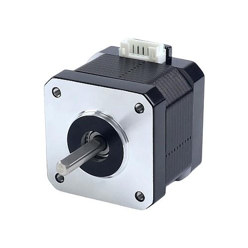
Stepper motors are brushless DC motors that divide a full rotation into a precise number of equal steps. They move in discrete increments rather than continuous rotation, making them ideal for applications requiring exact positioning without feedback sensors (open-loop control).
How Stepper Motors Work (Step-by-Step Motion)
Stepper motors operate using electromagnetic poles that are energized in sequence:
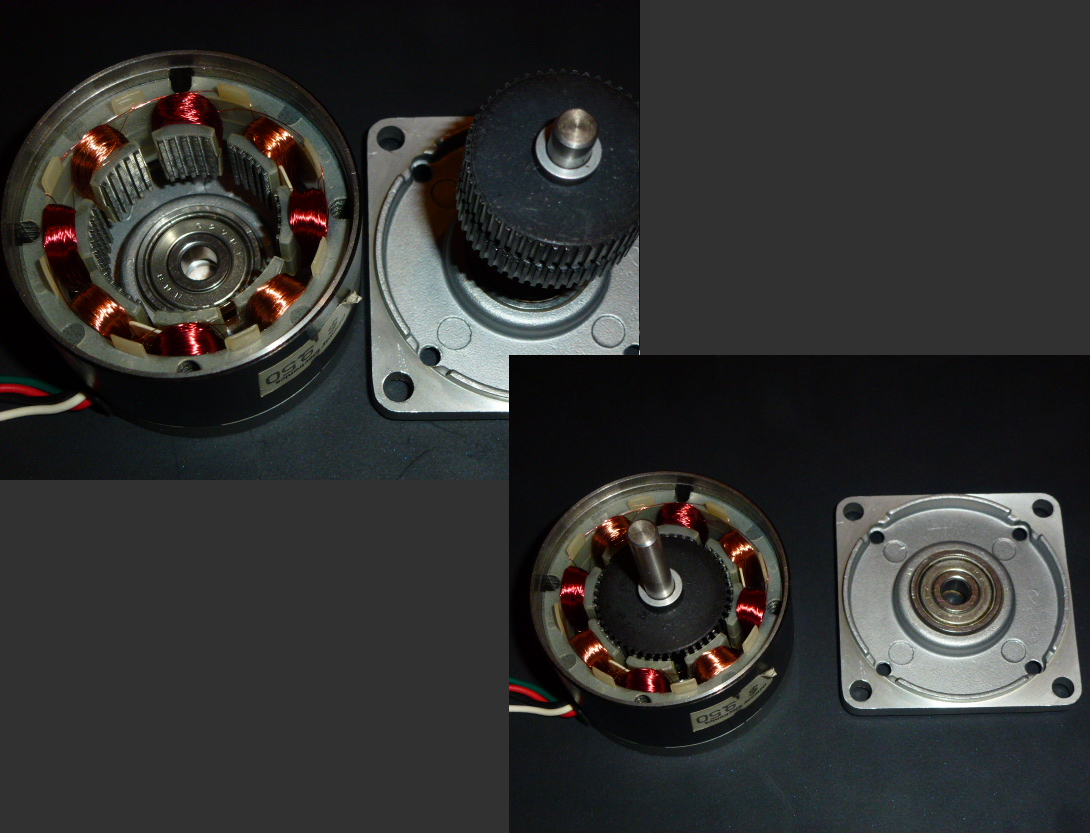
1. Stator Coils: The stationary part contains multiple electromagnet coils arranged around
the rotor. Common configurations have 4, 6, or 8 coils grouped into 2 or 4 phases.
2. Toothed Rotor: The rotating part is a permanent magnet or soft iron with many teeth
(typically 50-100 teeth). Some designs use permanent magnets for hybrid steppers.
3. Sequential Energizing: Coils are energized in a specific sequence. Each time the
energization pattern advances one step, the rotor moves one tooth pitch.
4. Step Angle: Most common steppers have 200 steps per revolution (360°/200 = 1.8° per step).
The rotor aligns its teeth with the currently energized stator poles.
5. Holding Torque: When stopped, energized coils create a magnetic force that resists
shaft rotation, providing holding torque even without movement.
Step Resolution Calculation:
Step Angle = 360° / (Number of Rotor Teeth × Number of Phases)
Example: 50 teeth, 4 phases = 360° / (50 × 2) = 1.8° per step
Stepper Motor Types
1. Bipolar Steppers: Have 4 wires, one coil per phase. Current direction must reverse
(requires H-bridge driver). Higher torque than unipolar of same size.
2. Unipolar Steppers: Have 5 or 6 wires with center-tapped coils. Simpler to drive
(no current reversal needed) but lower torque.
3. Full Step Mode: Energize one phase at a time or two adjacent phases. Provides full
rated torque and basic resolution (1.8° typical).
4. Half Step Mode: Alternate between 1-phase and 2-phase energizing. Doubles resolution
(0.9° per step) but torque varies.
5. Microstepping: Driver varies current in coils sinusoidally to create intermediate positions.
Can achieve 1/16 or 1/32 steps (0.1125° or finer), providing smooth motion but reduced holding torque.
Bipolar Stepper Motor
Four wires, requires H-bridge driver (A4988/DRV8825), delivers maximum torque
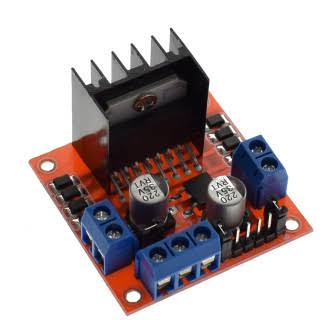
Stepper Driver Board
A4988 or DRV8825 driver handles current switching and microstepping
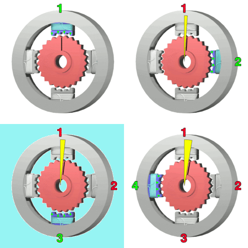
Step Sequence Animation
Visual representation of rotor movement as stator coils are energized sequentially
Applications in Robotics
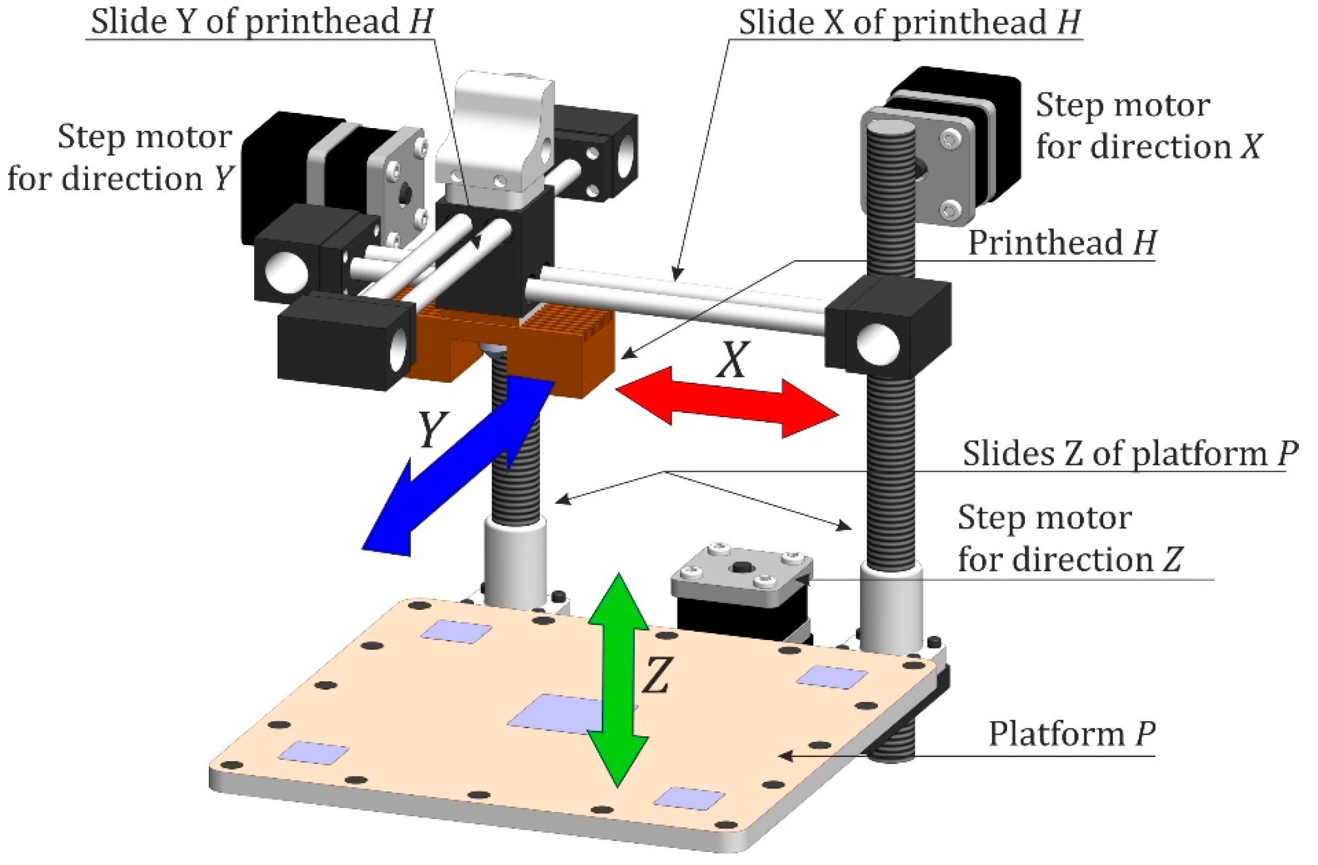
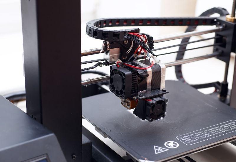
3D Printers
Stepper motors provide precise positioning for X, Y, Z axes and extruder feed mechanism
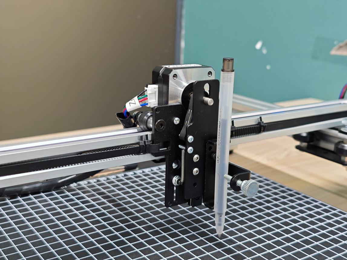
CNC Machines & Plotters
Multi-axis positioning for cutting, engraving, and drawing with sub-millimeter accuracy
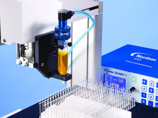
Laboratory Automation
Precise liquid handling, sample positioning, and automated testing equipment
Arduino Code for Stepper Control
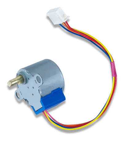
Stepper motors require a driver board (A4988, DRV8825, or ULN2003) to handle the current switching. The Arduino sends step pulses; each pulse moves the motor one step. Direction is controlled by a separate pin.
#include <Stepper.h>

// Define number of steps per revolution
// Common values: 200 (1.8° per step), 400 (0.9° per step)
const int stepsPerRevolution = 200;

// Initialize stepper library on pins 8, 9, 10, 11
// For ULN2003 driver: pins connect to IN1, IN2, IN3, IN4
Stepper myStepper(stepsPerRevolution, 8, 9, 10, 11);

void setup() {
  // Set motor speed in RPM (revolutions per minute)
  // Higher RPM = faster rotation but may lose steps if too fast
  myStepper.setSpeed(60);  // 60 RPM

  Serial.begin(9600);
  Serial.println("Stepper Motor Control");
  Serial.println("200 steps/rev, 1.8° per step");
}

void loop() {
  // One complete revolution clockwise
  Serial.println("Clockwise - 1 Revolution (200 steps)");
  myStepper.step(stepsPerRevolution);
  delay(1000);

  // One complete revolution counter-clockwise
  Serial.println("Counter-Clockwise - 1 Revolution");
  myStepper.step(-stepsPerRevolution);
  delay(1000);

  // Half revolution clockwise (180°)
  Serial.println("Clockwise - Half Revolution (100 steps = 180°)");
  myStepper.step(stepsPerRevolution / 2);
  delay(1000);

  // Quarter revolution counter-clockwise (90°)
  Serial.println("Counter-Clockwise - Quarter Revolution (50 steps = 90°)");
  myStepper.step(-stepsPerRevolution / 4);
  delay(1000);

  // Precise angle control example: 45°
  Serial.println("Rotate exactly 45 degrees");
  int stepsFor45Degrees = stepsPerRevolution / 8;  // 25 steps
  myStepper.step(stepsFor45Degrees);
  delay(2000);
}

// Alternative: Using A4988/DRV8825 driver (more efficient)
// Requires only 2 Arduino pins: STEP and DIR

const int stepPin = 2;
const int dirPin = 3;
const int enablePin = 4;  // Optional: LOW = enabled, HIGH = disabled

void setupA4988() {
  pinMode(stepPin, OUTPUT);
  pinMode(dirPin, OUTPUT);
  pinMode(enablePin, OUTPUT);

  digitalWrite(enablePin, LOW);  // Enable driver
}

void rotateA4988(int steps, bool clockwise) {
  digitalWrite(dirPin, clockwise ? HIGH : LOW);

  for (int i = 0; i < steps; i++) {
    digitalWrite(stepPin, HIGH);
    delayMicroseconds(500);  // Pulse width (adjust for speed)
    digitalWrite(stepPin, LOW);
    delayMicroseconds(500);  // Time between steps
  }
}Important: For smoother motion and acceleration control, consider using the AccelStepper library. It provides acceleration curves to prevent jerky motion and missed steps, especially important for CNC and 3D printing applications.
Hands-On Project: Robotic Claw
Build a 3-axis robotic claw arm using servo motors. This project demonstrates coordinated multi-servo control for pick-and-place operations, teaching concepts of inverse kinematics, sequential motion control, and practical servo positioning.
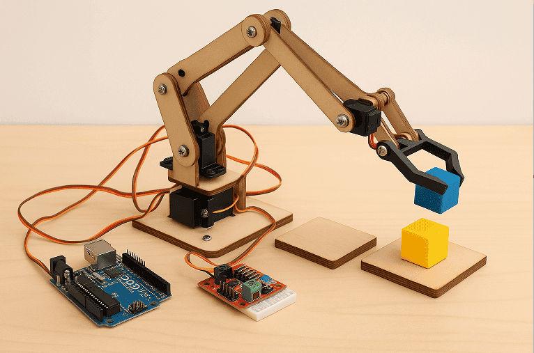
RoboClaw Controller
Advanced motor controller with current sensing and PID control for professional applications
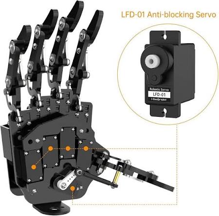
Multi-Servo Setup
Three servos working in coordination: base rotation, height control, and gripper actuation
Complete Assembly
Fully functional 3-DOF (degrees of freedom) robotic claw mechanism
Real-World Examples
Required Components
• Microcontroller: Arduino Uno or compatible (Nano, Mega)
• Servo Motors: 3× SG90 or MG996R servos (torque rating depends on claw weight)
• Power Supply: External 5-6V power supply (2A minimum for 3 servos)
• Mechanical Parts: Robotic claw kit or 3D printed components
• Wiring: Jumper wires, breadboard (optional)
• Capacitor: 470µF-1000µF electrolytic capacitor (across power supply)
• Optional: Potentiometers for manual control, push buttons for automation
Wiring Diagram
Power Connections (Critical!):
• External Power Supply (+) → Servo VCC (all servos)
• External Power Supply (−) → Arduino GND AND Servo GND (common ground)
• Large capacitor (470µF+) across power supply to smooth voltage spikes
• Never power multiple servos from Arduino 5V pin (insufficient current)
Signal Connections:
• Servo 1 (Claw Gripper) Signal → Arduino Pin 3
• Servo 2 (Height/Elbow) Signal → Arduino Pin 4
• Servo 3 (Base Rotation) Signal → Arduino Pin 5
Why Separate Power? Three servos under load can draw 1-2A total, far exceeding
Arduino's 500mA regulator capacity. Insufficient current causes brownouts and resets.
Complete Arduino Code
// 3-Axis Robotic Claw with Servo Motors
// Demonstrates coordinated multi-servo control for pick-and-place
// Code by Aryaman Kumar

#include <Servo.h>

// Create servo objects for each axis
Servo servoClaw;    // Gripper: opens/closes the claw
Servo servoHeight;  // Elbow: raises/lowers the claw
Servo servoTurn;    // Base: rotates the claw horizontally

// Initial positions (adjust these for your specific claw design)
int clawAngle = 150;   // 150° = open position
int heightAngle = 160; // 160° = raised position
int turnAngle = 0;     // 0° = center/home position

// Movement function declaration (defined below)
int move(Servo servoTemp, int currentAngle, int desiredAngle);

void setup() {
  Serial.begin(9600);
  Serial.println("Robotic Claw Initialized");

  // Attach servos to PWM pins
  servoClaw.attach(3);
  servoHeight.attach(4);
  servoTurn.attach(5);

  // Move all servos to initial positions slowly
  Serial.println("Moving to home position...");
  heightAngle = move(servoHeight, heightAngle, heightAngle);
  turnAngle = move(servoTurn, turnAngle, turnAngle);
  clawAngle = move(servoClaw, clawAngle, clawAngle);
  delay(1000);

  // === PICK-AND-PLACE SEQUENCE ===

  // Object 1: Pick up from right side (90°)
  Serial.println("Approaching Object 1 (right side)");
  turnAngle = move(servoTurn, turnAngle, 90);  // Rotate to 90°
  delay(1000);

  Serial.println("Lowering claw");
  heightAngle = move(servoHeight, heightAngle, 90);  // Lower arm
  delay(1000);

  Serial.println("Closing gripper");
  clawAngle = move(servoClaw, clawAngle, 10);  // Close claw (10° = closed)
  delay(1000);

  Serial.println("Lifting object");
  heightAngle = move(servoHeight, heightAngle, 160);  // Raise arm
  delay(1000);

  // Place Object 1 in center container
  Serial.println("Rotating to container");
  turnAngle = move(servoTurn, turnAngle, 0);  // Rotate to center
  delay(1000);

  Serial.println("Lowering to container");
  heightAngle = move(servoHeight, heightAngle, 140);  // Lower slightly
  delay(1000);

  Serial.println("Releasing object");
  clawAngle = move(servoClaw, clawAngle, 150);  // Open claw
  delay(1000);

  Serial.println("Retracting");
  heightAngle = move(servoHeight, heightAngle, 160);  // Raise to home
  delay(1000);

  // Object 2: Pick up from left side (160°)
  Serial.println("Approaching Object 2 (left side)");
  turnAngle = move(servoTurn, turnAngle, 160);  // Rotate to 160°
  delay(1000);

  Serial.println("Lowering claw");
  heightAngle = move(servoHeight, heightAngle, 90);
  delay(1000);

  Serial.println("Closing gripper");
  clawAngle = move(servoClaw, clawAngle, 10);
  delay(1000);

  Serial.println("Lifting object");
  heightAngle = move(servoHeight, heightAngle, 160);
  delay(1000);

  // Place Object 2 in center container
  Serial.println("Rotating to container");
  turnAngle = move(servoTurn, turnAngle, 0);
  delay(1000);

  Serial.println("Lowering to container");
  heightAngle = move(servoHeight, heightAngle, 140);
  delay(1000);

  Serial.println("Releasing object");
  clawAngle = move(servoClaw, clawAngle, 150);
  delay(1000);

  Serial.println("Retracting to home");
  heightAngle = move(servoHeight, heightAngle, 160);
  delay(1000);

  Serial.println("Sequence complete!");
}

void loop() {
  // Empty - sequence runs once in setup()
  // Could add manual control or sensor-triggered automation here
}

/**
 * Smooth servo movement function
 * Gradually moves servo from current angle to desired angle
 * Prevents jerky motion and reduces mechanical stress
 *
 * @param servoTemp - The servo object to move
 * @param currentAngle - Current position in degrees
 * @param desiredAngle - Target position in degrees
 * @return Final angle reached (same as desiredAngle)
 */
int move(Servo servoTemp, int currentAngle, int desiredAngle) {
  if (currentAngle < desiredAngle) {
    // Move clockwise (increasing angle)
    while (currentAngle <= desiredAngle) {
      servoTemp.write(currentAngle);
      currentAngle++;
      delay(10);  // Delay controls movement speed (lower = faster)
    }
  }
  else {
    // Move counter-clockwise (decreasing angle)
    while (currentAngle >= desiredAngle) {
      servoTemp.write(currentAngle);
      currentAngle--;
      delay(10);
    }
  }

  return currentAngle;
}
How It Works
The move() function implements incremental motion: instead of jumping
instantly from one angle to another, it moves one degree at a time with 10ms delays. This creates
smooth, controlled motion and prevents:
• Mechanical shock and gear damage
• Power supply voltage sags from sudden current spikes
• Object slipping from jerky movements
The sequence demonstrates state machine programming: each operation (turn, lower, grip,
lift) completes before the next begins, ensuring reliable pick-and-place operations.
Customization & Extensions
Adjust for Your Hardware:
• Modify angle values (90°, 140°, 150°, etc.) to match your claw's physical limits
• Test each servo individually before running the full sequence
• Adjust delay(10) in move() for faster/slower motion
Add Manual Control:
• Connect 3 potentiometers (one per servo) for real-time position control
• Read analog values: angle = map(analogRead(pot), 0, 1023, 0, 180);
Sensor Integration:
• Add ultrasonic sensor for object detection
• Use IR sensors to detect object presence in gripper
• Implement color sensor for object sorting
Advanced Features:
• Implement inverse kinematics for Cartesian (X,Y,Z) control
• Add acceleration/deceleration curves for professional motion
• Expand to 6 DOF (degrees of freedom) for full 3D manipulation
• Create teaching mode: record positions, replay sequences